
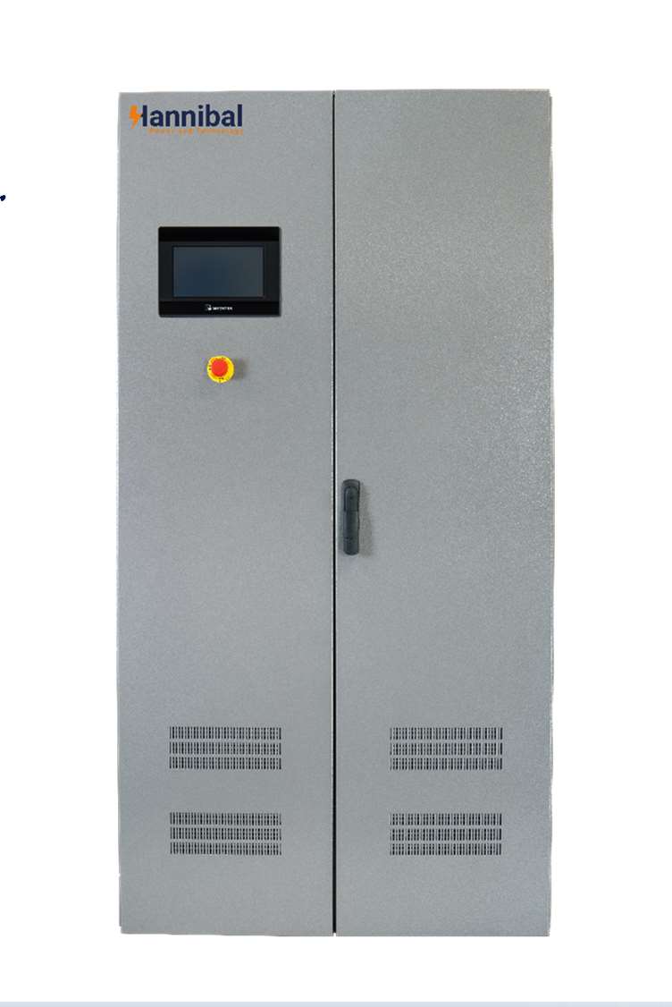
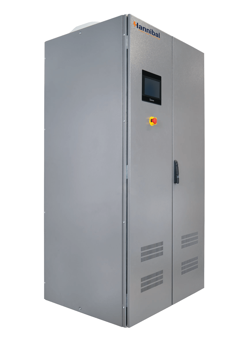
This industrial frequency converter is a high-efficiency VFC (Variable Frequency Converter) designed to adapt electrical power for seamless operation across different grid standards. It serves as a reliable 60Hz to 50Hz converter for export equipment, ensuring regional compatibility while enhancing energy efficiency and reducing mechanical stress. Available in static (solid-state) or rotary (motor-generator) designs, it delivers a stable variable frequency power supply for precise motor speed control, enabling flexible and optimized industrial performance in diverse power conditions.
Front panel analogue meters (72×72, class 1.5) .
Transducers 4-20mA
Additional volt-free contacts
Modbus/TCP
IEC61850 protocol monitoring software
Mimic panel:
Passive mimic of the system
Active mimic with integrated LEDs Lamp indicator on front panel (22 mm diameter)
External ingress protection up to IP42
Top cable entry
Specified color of panels
Special feet height (200mm or 300mm)
Special keylock
Non-magnetic gland plate (brass or aluminum)
Specified cabinet identification (tag, nameplate)
Industrial frequency converter, also known as a frequency changer, is a device that alters the electrical frequency of power supplied to industrial machinery and equipment. It plays a crucial role in various industrial applications where equipment designed for one frequency needs to be operated on a different frequency power supply.
Frequency converters can be static (electronic circuits) or rotary (motor-generator). They enable regional compatibility, improve energy efficiency, reduce equipment wear, and enhance motor speed control for smoother, more flexible industrial operations.
Strengthened reliability:
Increased availability:
Industrial grade inverters
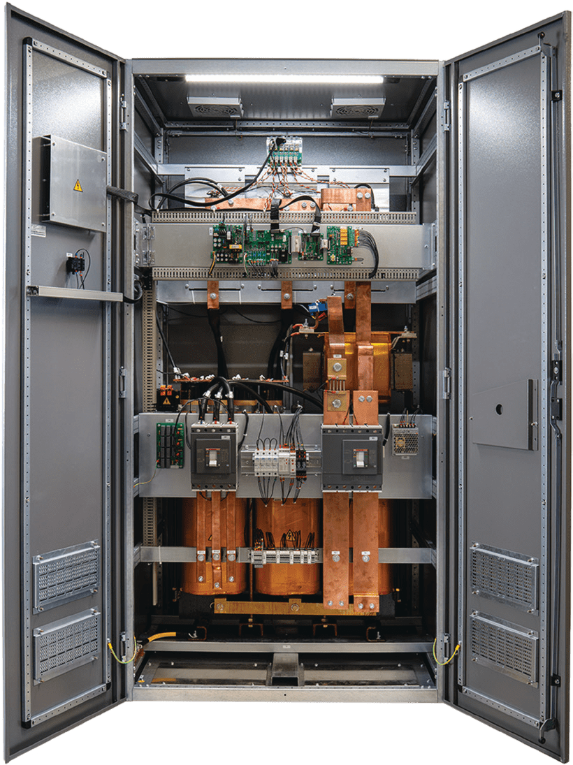
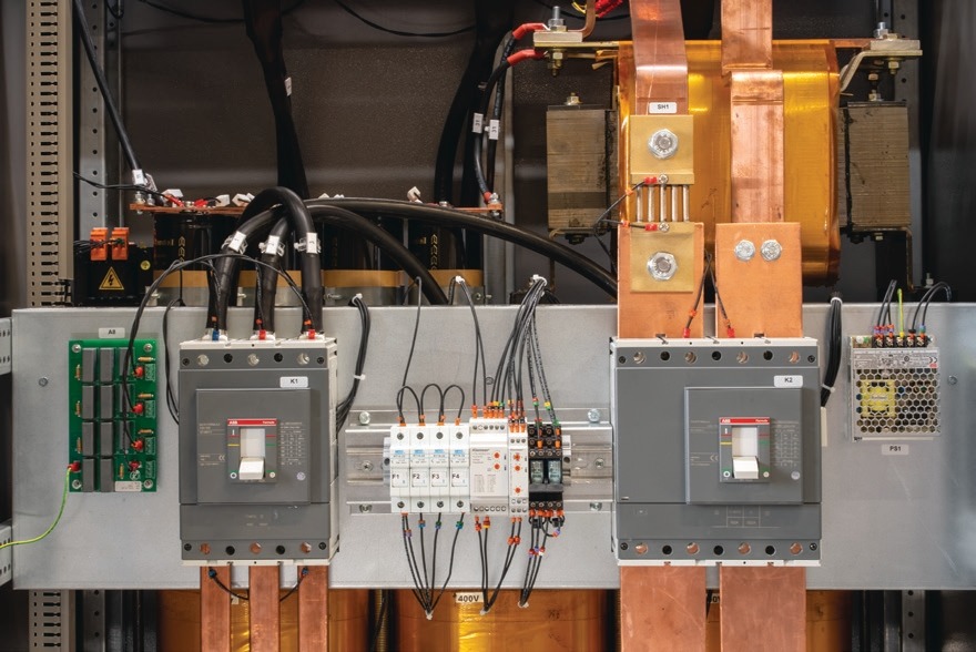
Hannibal system range is based on SCR/IGBT technology with proven digital control. It is available from 2.5 to 250 kVA in single-phase output version and from 5 to 2000 kVA in three-phase output version. It is configurable with a set of industrial options such as custom protection devices, bypass transformer and/or stabilizer, various communication solutions, etc.
Designed as an industrial system, it includes most frequently specified features as default, for example dual cooling channel, input and output transformers, conformal coating of all printed circuit boards, halogenfree flame retardant internal cables.
The architecture of the system allows the segregation of different pre-defined functions that help to increase personnel safety on site as well as improve overall system availability.
| Technical Data | Ratings |
|---|---|
|
Rectifier Bridge Topology |
Thyristor 6 Pulses – Standard- Thyristor 12 Pulses- Optional- IGBT – Optional |
|
Input Voltage -Single Phase |
110/120/200/220/240/277 V |
|
Input Voltage-Three Phase |
208/220/240/380/400/415/480 V |
|
Voltage tolerance |
+/- 15 % |
|
Efficiency |
90% to 95% |
|
Frequency |
50 Hz (60 Hz) |
|
Frequency tolerance |
+/- 5 % |
|
Frequency range
(temporary) |
<5% 1Ph- <2% 3Ph |
|
Total harmonic
distorsion (THD) |
<30% for 6 pulses Rectifier – <12%
for 12 Pulses version |
|
Inrush current |
≤ 10 x In(4) |
|
Ripple |
<5% 1Ph- <2% 3Ph |
| Technical Data | Ratings | |
|---|---|---|
|
IGBT with output isolation Transformer |
Inverter Bridge Topology |
|
|
AC Voltage- Single phase |
1 x 230 V (220, 240) ; 1 x 110 V (115, 120)(4)
|
|
|
AC voltage
• Three phase |
3 x 400 V (380, 415) ; 3 x 220 V (200, 208, 230)(4) |
|
|
AC Voltage Tolerance |
1% |
|
|
Frequency |
50 Hz (60 Hz) |
|
|
Frequency Tolerance |
+/- 0.05 % |
|
|
Inverter overload capability -1 minute |
150 % of nominal power |
|
|
Inverter overload capability – 10 minute |
125%
of nominal power |
|
|
Short circuit clearance (in % of nominal current) – 1-ph output |
250 % / 100ms – 175% / 5s |
|
|
Short circuit clearance (in % of nominal current) – 3-ph output Ph-N |
315 % / 100 ms – 220 % / 5 s |
|
|
Short circuit clearance (in % of nominal current) 3-ph output Ph-Ph |
190 % / 100 ms – 135 % / 5 s |
|
|
Harmonic voltage distortion – With 100 % linear load |
< 3% |
|
|
Harmonic voltage distortion – With 100 % non-linear load |
SS as per IEC/EN 62040-3 |
|
|
Power Factor |
0.8 |
|
|
Efficiency |
90% |
|
|
Allowable crest factor |
up to 3/1 |
|
| Technical Data | Ratings |
|---|---|
|
IEC62040-1:2017 |
Uninterruptible power systems
(UPS) – Part 1: Safety requirements |
|
IEC62040-2:2016 |
Uninterruptible power systems (UPS) – Part 2:
Electromagnetic compatibility (EMC) requirements |
|
IEC62040-3:2011 |
Uninterruptible power systems (UPS) – Part 3:
Method of specifying the performance and test
requirements |
|
IEC61439-1:2011 |
Low voltage switchgear and controlgear
asse blies – Part 1: General rules |
|
IEC60529:1989
+AMD1:1999 |
Degrees of protection provided
by enclosures (IP Code) |
|
IEC60076-11:2004 |
Power transformers – Part 11: Dry type transformers |